Wave Diffraction for the Confused First Year
Diffraction patterns and phasors are one of the most confusing topics for students to learn intuitively. This short post is intended to help Cambridge Physics IA students understand why we use phasors, how to use them, and how to derive the correct expressions for diffraction pattern intensities that you learn about in the Waves & Quantum Waves lecture course. You can think of it as a supplement to the lecture notes (available here). I recommend you read that first. I also recommend this post on StackExchange, on which parts of this write-up are based.
After a refresher on what a phasor is, we will use them to derive expressions for diffraction intensities for the following cases:
- One Point Source
- Double Slits (Two Point Sources)
- Diffraction Grating (Multiple Point Sources)
- Single-Slit Diffraction (Infinitely Many Point Sources)
- Double Slits with Finite Width
In addition to phasor derivations, we will also see how to derive the final two expressions via integration.
Why Phasors?
Whilst using phasors makes sense for circuit theory (especially when dealing with an alternating current), it is not completely clear how they are useful for working out a diffraction pattern. The basic reason why is that it lets us bypass long algebraic derivations with diagrams, and relate finding the intensity at a point on a screen to graphically ‘connecting’ arrows with different orientations and lengths. Since phasors are complex numbers (which are vectors), this describes the effect of constructive & destructive interference of waves from multiple sources arriving at a point on a screen.
You should know that a wave \(\psi\) is described by an expression of the form \(\psi = A\cos(\omega t - k x)\). Just like for AC circuits in electronics, we will introduce a complex variable \(Z = Ae^{i(\omega t - k x)}\), and set \(\psi = \text{Re} (Z)\). Thus, we can obtain interference effects by adding up a bunch of complex numbers and taking their real part. We will later see that in practice it is easier to just consider the modulus \(\| Z \|\) and square it to obtain the intensity.
One Point Source
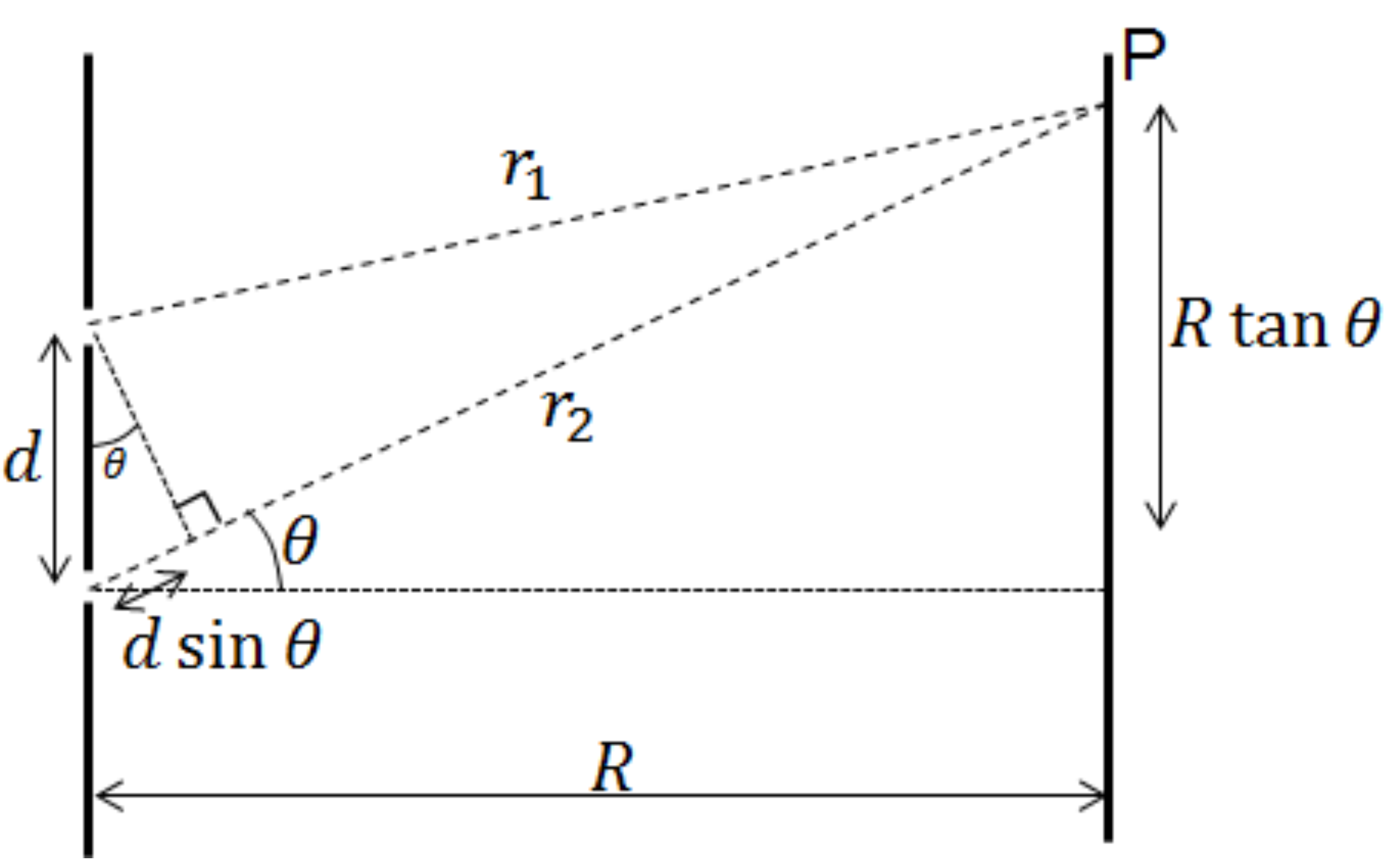
To make this more concrete, let’s initially consider a single wave coming from a point source (of infitesimally small width, so we don’t get single-slit diffraction), and pick some point on a screen at a distance \(x\). We then consider the amplitude of this wave: it is going to be given to us by \(A\cos(\omega t - k x)\). Our phasor is complex number \(Z\), and the amplitude of the wave is then the real part of \(Z\). You can see this (as a function of \(x\) and \(t\)) in the animation below:
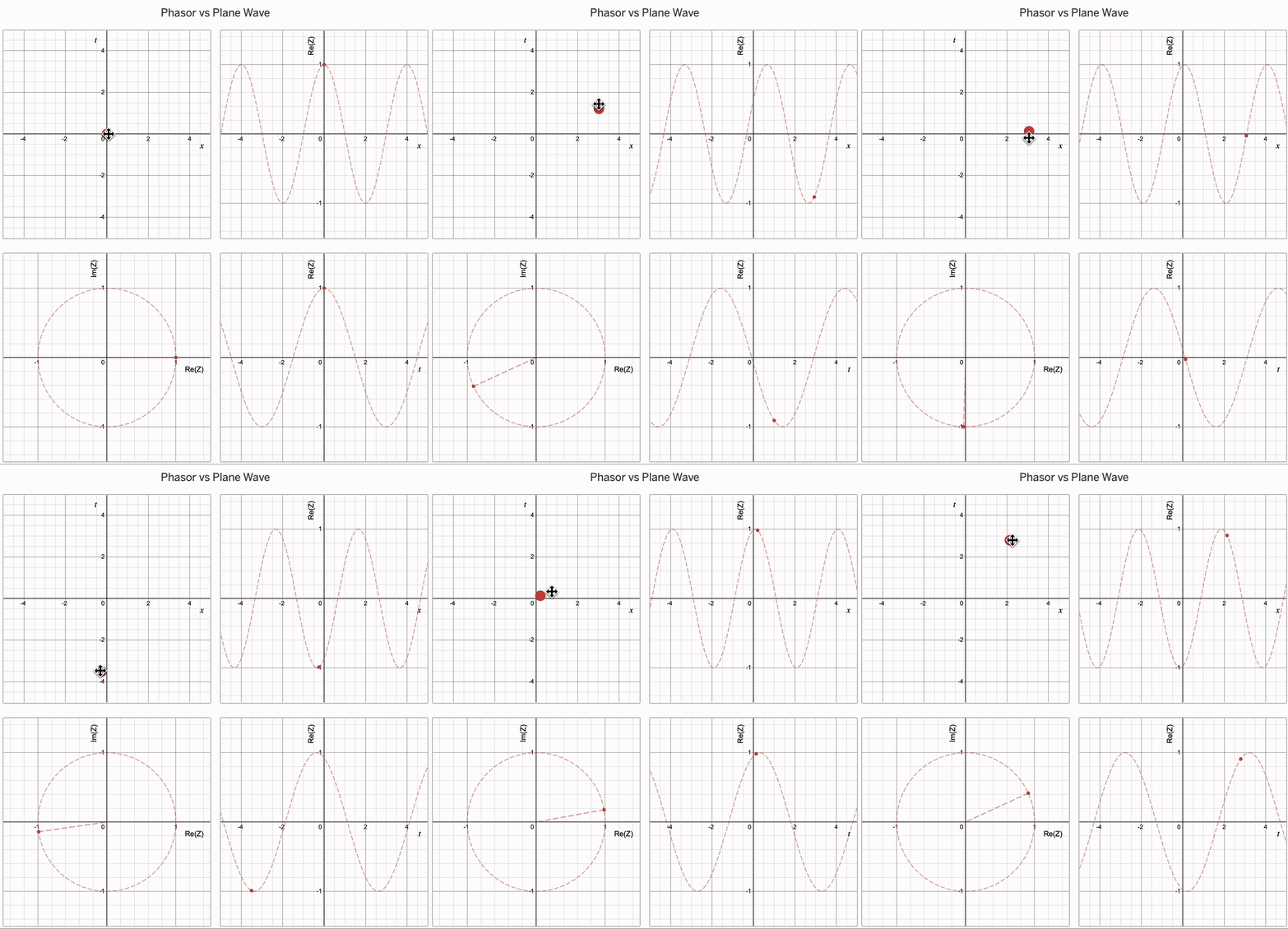
Notably, if we set \(x = r\) and vary \(t\), it will give us the amplitude at some point \(r\) away as a function of time. On the other hand, if we set \(t = t'\) then the graph of \(\text{Re}(Z)\) against \(x\) gives us the amplitude of the arriving wave on the whole screen at some instant in time \(t'\). We could then transform the resulting graph into one of amplitude vs. angular displacement by substituting for \(x\) using \(R = x \sin \theta\).
In a diffraction experiment, however, we are interested in the intensity (i.e. brightness) rather than amplitude of the arriving waves. The intensity is proportional to the square of the amplitude as \(I \propto \psi^2\), or in terms of our phasor \(I \propto \text{Re}(Z)^2\). We also tend to not care about the time-dependence, meaning we usually average it out when finding the expression for intensity. So we can calculate the time-averaged intensity \(\bar{I}(x)\) from a point source as:
\[\bar{I}(x) \propto \frac{1}{T} \int^T_0 A^2 \cos^2(\omega t - k x) dt \propto \frac{A^2}{2}\]In other words, for a point source every position on the screen receives the same intensity of light, which makes sense as there are no interference effects.
Two Slits (Two Point Sources)
The two slit diffraction pattern is the result of waves from two point sources arriving at the screen, where there is now interference caused by a difference in the distances travelled from the sources to the screen. We have two phasors \(Z_1= A_1 e^{i(\omega t_1 - k r_1)}\) and \(Z_2= A_2 e^{i(\omega t_2 - k r_2)}\), and the amplitude of the resulting wave is given by \(\text{Re}(Z) = \text{Re}(Z_1 + Z_2)\). I have changed the \(x\) coordinates to \(r\) for consistency with the lecture notes.
Here, we make some assumptions: \(R\) is much larger than the slit spacing \(d\), so the distances from the two point sources to the screen are are \(r_1 = r\), and \(r_2 \simeq r + d \sin \theta\). We will also say that the waves leave the two point sources at the same time, so \(t_1 = t_2 = t\), and their individual amplitudes are the same giving \(A_1 = A_2 = A\). Our phasor at the point of angular displacement \(\theta\) is therefore given by:
\[Z_1 + Z_2 = Ae^{i(\omega t - k r)} + Ae^{i(\omega t - k(r + d \sin \theta))} = Ae^{i(\omega t - k r)} (1 + e^{- i k d \sin \theta})\]At this point you would usually draw \(Z\) and use the cosine rule to derive the expression for \(I(\theta)\), but we will first proceed algebraically. We can again take the real part of this expression, which will be given by:
\[\text{Re}(Z) = A \cos (\omega t - k r) + A \cos (\omega t - k(r + d \sin \theta)) = 2A \cos (\omega t - kr + \frac{1}{2} kd \sin \theta) \cos ( \frac{1}{2} kd \sin \theta)\]Thus, the time-averaged intensity is given by:
\[\begin{aligned} \bar{I}(\theta) &\propto \frac{4A^2}{T} \int^T_0 \cos^2 (\omega t - kr + \frac{1}{2} kd \sin \theta) \cos^2 ( \frac{1}{2} kd \sin \theta) dt \\ &\propto 2A^2 \cos^2 ( \frac{1}{2} kd \sin \theta) + \frac{2A^2}{T} \cos^2 ( \frac{1}{2} kd \sin \theta) \int^T_0 \cos (2\omega t - 2kr + kd \sin \theta) dt \\ &\propto 2A^2 \cos^2 ( \frac{1}{2} kd \sin \theta) \end{aligned}\]Again, averaging the expression with respect to time has ‘flushed out’ terms dependent on \(\omega t - kr\). In principle, you could calculate an integral like this for any number of slits, but the point of this article is to show you how to avoid doing so.
Using Phasors
Notice that in the previous expression for \(Z_1 + Z_2\) we have split up the complex number into a product of two complex numbers. When the number of slits increases we will always be able to do this, and the phasor \(Z = Z_1 + Z_2 + ... + Z_N\) will factor into \(e^{i(\omega t - kr)}\) (which I will call the overall phase) and \(Z(\theta)\):
\[Z = e^{i(\omega t - kr)} \times Z(\theta)\]Since \(Z(\theta)\) is another complex number, we can write it in polar form as \(Z(\theta) = e^{i \alpha} \sqrt{I(\theta)}\), where \(\sqrt{I(\theta)}\) is the ‘length’ of the phasor, and \(e^{i \alpha}\) is some additional phase. Since \(t\) in our overall expression is arbitrary, we can (without loss of generality) absorb this into the overall phase (setting \(t \rightarrow t - \frac{\alpha}{\omega}\)) to obtain:
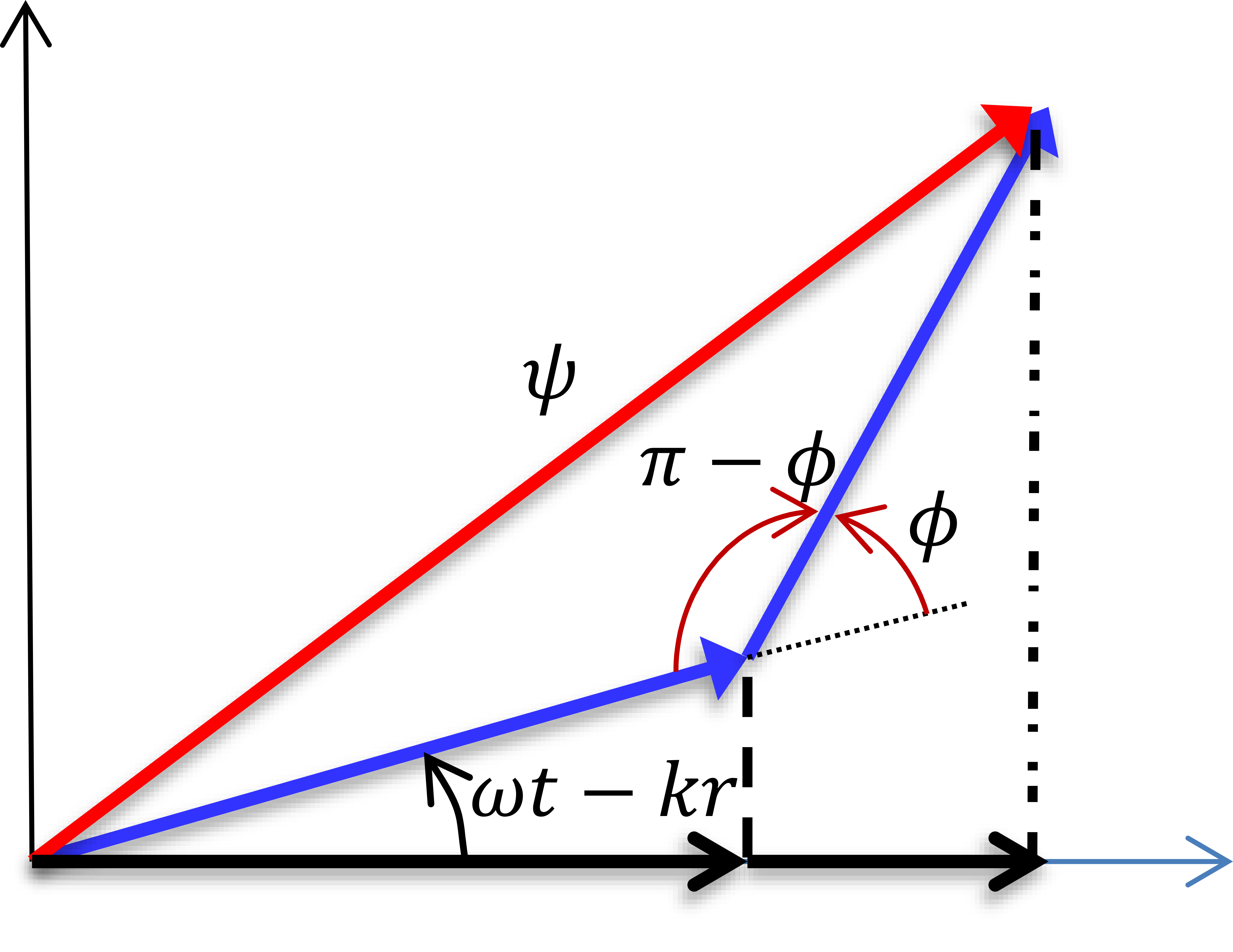
\[Z = e^{i(\omega t - kr)} \times \sqrt{I(\theta)}\]Finally, when we draw out a phasor for \(Z\) this will be given by some arrow of length \(\sqrt{I(\theta)}\) initially at an angle \(\omega t - kr\) to the origin, which then rotates counterclockwise with \(t\) increasing. Notice that for some value of \(t\) (i.e. \(t = \frac{kr}{\omega}\)) the amplitude will be equal to the length of this arrow, i.e. \(- \| Z \| \leq \text{Re}(Z) \leq \| Z \|\). So we can think of the modulus of \(Z\) as a bound for the amplitude of the wave observed at \(\theta\), and its square as a bounding value for the intensity. Time averaging the intensity will then give a value proportional to this bound, so we can just calculate \(\| Z \|\) to identify \(I(\theta)\).
The upshot of the above is that we can find the square root of the intensity from the modulus of the resulting phasor \(Z\), and we can then find the intensity from taking the modulus square \(\| Z \|^2\). We can then find the time-averaged intensity from \(\bar{I}(\theta) = \frac{I(\theta)}{2} = \frac{\| Z \|^2}{2}\).
Let’s try this for the double slit. The modulus of \(Z\) is given by:
\[\begin{aligned} \| Z \| & = \sqrt{ A^2 (1 + e^{-ikd \sin \theta } ) (1 + e^{ikd \sin \theta } ) } \\ & = \sqrt{A^2(2 + e^{ikd \sin \theta } + e^{-ikd \sin \theta } )} \\ & = A \sqrt{2} \sqrt{1 + \cos (kd \sin \theta)} \\ & = A \sqrt{2} \sqrt{2 \cos^2 (\frac{1}{2} kd \sin \theta) } \\ & = 2A \cos ( \frac{1}{2} kd \sin \theta ) \end{aligned}\]Which returns the correct expression for \(\bar{I}(\theta)\). Finally, we could have avoided all of this algebra by following the derivation given in the lecture notes, i.e. drawing out the phasor and using the cosine rule to find the length of the \(Z\) (given by the red line in the diagram):
Diffraction Gratings (\(N\) Point Sources)
We can use this method for finding the expression for \(I(\theta)\) when there are multiple slits present. Algebraically, this means we have \(Z = Z_0 + ... + Z_{N-1}\), and \(Z_m = Ae^{i(\omega t - kr - m \delta)}\), where \(\delta = kd \sin \theta\). This gives us the following expression for \(Z\):
\[Z = A e^{i(\omega t - kr)} \times \sum_{m=0}^{N-1} e^{- i m \delta}\]We now have two cases. The first is when \(\delta = kd \sin \theta = 2 \pi n\), with \(n\) integer. Then, \(e^{- i m \delta} = 1\) and the sum on the right hand side evaluates to \(N\), meaning that \(Z = A N e^{i(\omega t - kr)}\), and we have points of maximum intensity. The second case is when \(\delta \neq 2 \pi n\). Then the right-hand side is a geometric sequence, which we can sum as:
\[\sum_{m=0}^{N-1} e^{- i m \delta} = \frac{1 - e^{- i N \delta}}{1 - e^{- i \delta} }\]In the second case, the geometric sequence will evaluate to zero whenever \(\delta = kd \sin \theta = \frac{2 \pi p}{N}\), with \(p \in \{1, 2, ..., N-1 \}\). Therefore, we get \(N-1\) minima between each \(\delta = 2 \pi n\) maxima, and smaller subsidiary maxima (of which there are \(N - 2\)) between each minima. This is completely in agreement with what you have been told in your lectures.
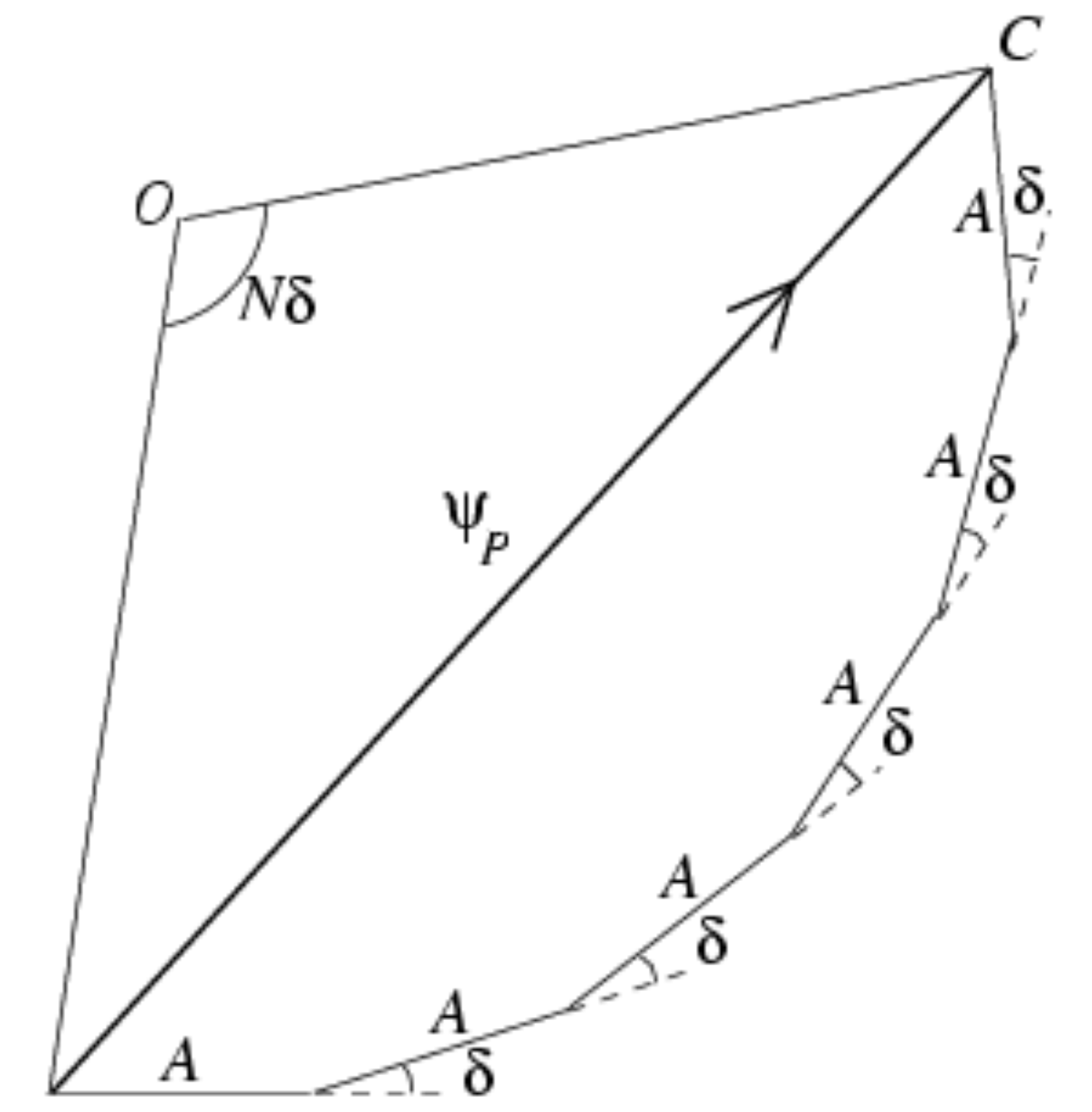
Again, we could have worked this out through a diagram, by joining together \(N\) arrows each displaced by an angle of \(\delta\). When the angle \(\delta\) is a multiple of \(2 \pi\), all of the arrows are in parallel hence we get constructive interference and an overall arrow of length \(AN\). On the other hand, if \(\delta = \frac{2 \pi p}{N}\), once we have joined all of the arrows together we are back at the origin, i.e. the resulting phasor has zero length and we are at a minimum. The corresponding diagram then forms a regular polygon with the exterior angles equal to \(\delta = \frac{2 \pi p}{N}\).
Diffraction Gratings in the \(N \rightarrow \infty\) Limit
We can use the result for the finite \(N\) diffraction grating to obtain two further expressions – one when the number of slits gets very large (i.e. \(N \rightarrow \infty\), but their spacing \(d\) is kept constant), and another when the number of slits gets infinitely large and the slits get infinitely small (\(N \rightarrow \infty\) with \(d \rightarrow 0\), which will turn out to be the slit of finite width). Here, you have to be EXTREMELY CAREFUL, because the two limits correspond to physically distinct phenomena – it would be flat out wrong to say that a diffraction by a grating with very many spacings is the same as single-slit diffraction!
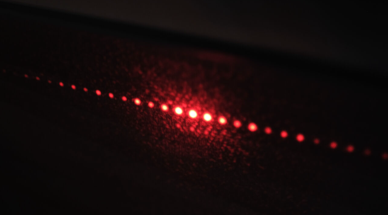
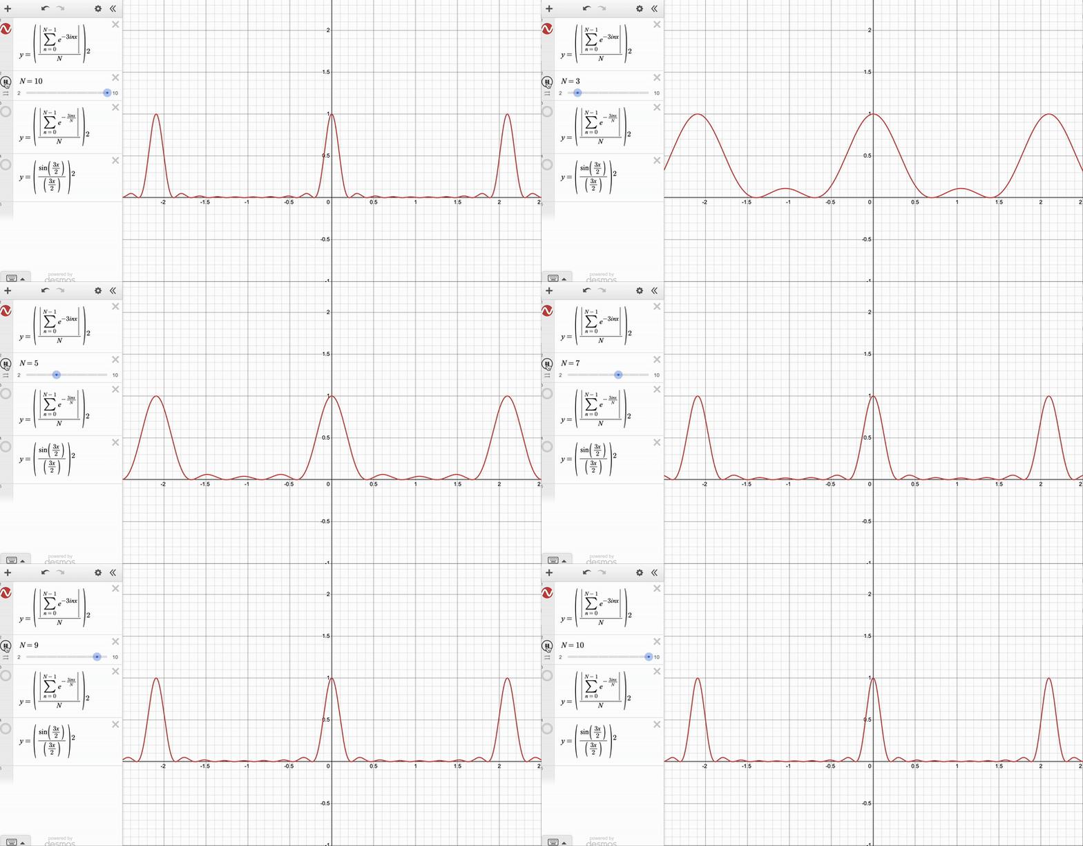
For the \(N \rightarrow \infty\), \(d\) constant case notice that the angular displacement between the central \(\delta = 0\) maximum and its closest \(\delta = kd \sin \theta = \frac{2 \pi }{N}\) minimum is \(\Delta \theta = \frac{2 \pi}{N}\), which gives us the width of the maxima (proportional to \(\frac{1}{N}\)). We can also see that the intensity of the \(\delta = \frac{2 \pi p}{N}\) maxima goes as \(\| Z \|^2 \propto N^2\). We can therefore say that as \(N \rightarrow \infty\), the maxima become sharper (their width approaches \(0\)), and their intensities are much larger than those of the subsidiary maxima. So in this limit, the pattern tends towards sharp points at \(kd \sin \theta = 2 \pi n\) with no maxima inbetween.
For the other case, we will make the diffraction grating spaces very small, and set \(d = \frac{a}{N-1}\) (where \(a\) is the overall width of the grating). Each wave will also have an amplitude of \(A =\frac{A_{\text{max}}}{N}\). The overall phase difference between the top and bottom of the grating is given by \(\phi = (N-1) \delta = k a \sin \theta\). There are \(N\) spacings overall, and our expression for \(\| Z \|\) is given by:
\[\| Z \| = \left\| \frac{A_{\text{max}}}{N} \sum_{m=0}^{N-1} e^{\frac{- i \phi m}{N-1} } \right\|\]Let’s take the \(N \rightarrow \infty\) limit of this. Then, we can approximate the sum by an integral, as follows:
\[\begin{aligned} \| Z \| &\simeq \left\| \frac{A_{\text{max}}}{N} \int_{0}^{N-1} e^{\frac{- i \phi x }{N-1} } dx \right\| \\ & \simeq \frac{A_{\text{max}}}{N} \frac{N - 1}{\phi} \| e^{- i \phi} - 1 \| \\ & \simeq \frac{N-1}{N} \frac{A_{\text{max}}}{\phi} \sqrt{(e^{- i \phi} - 1) (e^{i \phi} - 1)} \\ & \simeq \frac{N-1}{N} \frac{A_{\text{max}}}{\phi} \sqrt{2 - e^{i \phi} - e^{-i \phi} } \\ & \simeq \frac{N-1}{N} \frac{A_{\text{max}}}{\phi} \sqrt{2 - 2 \cos \phi } \\ & \simeq \frac{N-1}{N} \frac{A_{\text{max}}}{\phi} \sqrt{4 \sin^2 (\frac{\phi}{2}) } \\ & \simeq \frac{N-1}{N} \frac{A_{\text{max}}}{\phi / 2} \sin (\frac{\phi}{2}) \end{aligned}\]If we now square this and take the limit of \(N \rightarrow \infty\), we finally obtain:
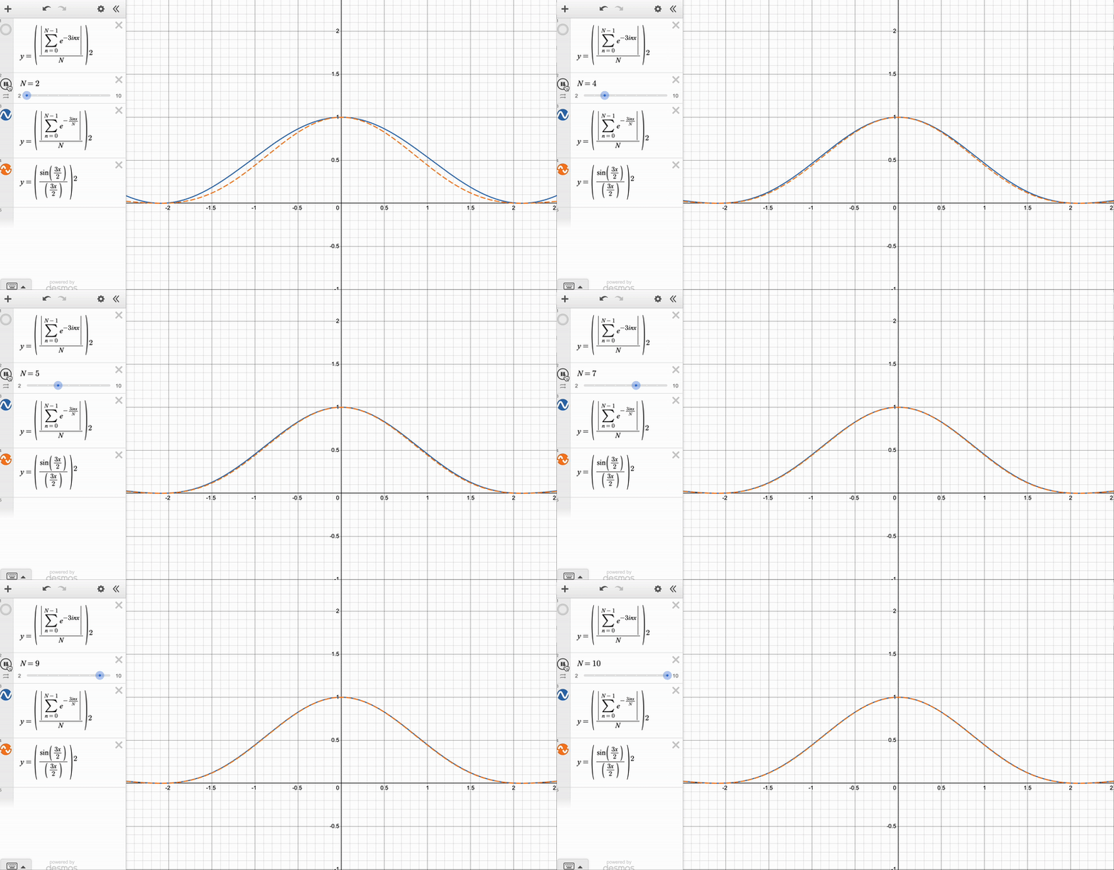
\[I (\theta) \simeq \left( \frac{A_{\text{max}}}{\phi / 2} \sin (\frac{\phi}{2}) \right)^2 \simeq A_{\text{max}}^2 \text{sinc}^2(\frac{\phi}{2})\]Which again is the expression for single slit diffraction (of width \(a\)) which you have seen in your lectures! Again, this approach is complimentary to the diagrammatic method given in the handout. In the diagrammatic method, we have also split the slit of finite width into infinitely many point sources of infitesimal size (the diagram then tends towards an arc of a circle), and used geometry to find the length \(\| Z \|\) of the resulting phasor.
We can see the convergence clearly with these animations, which I made on Desmos:
Diffraction Patterns via Integration
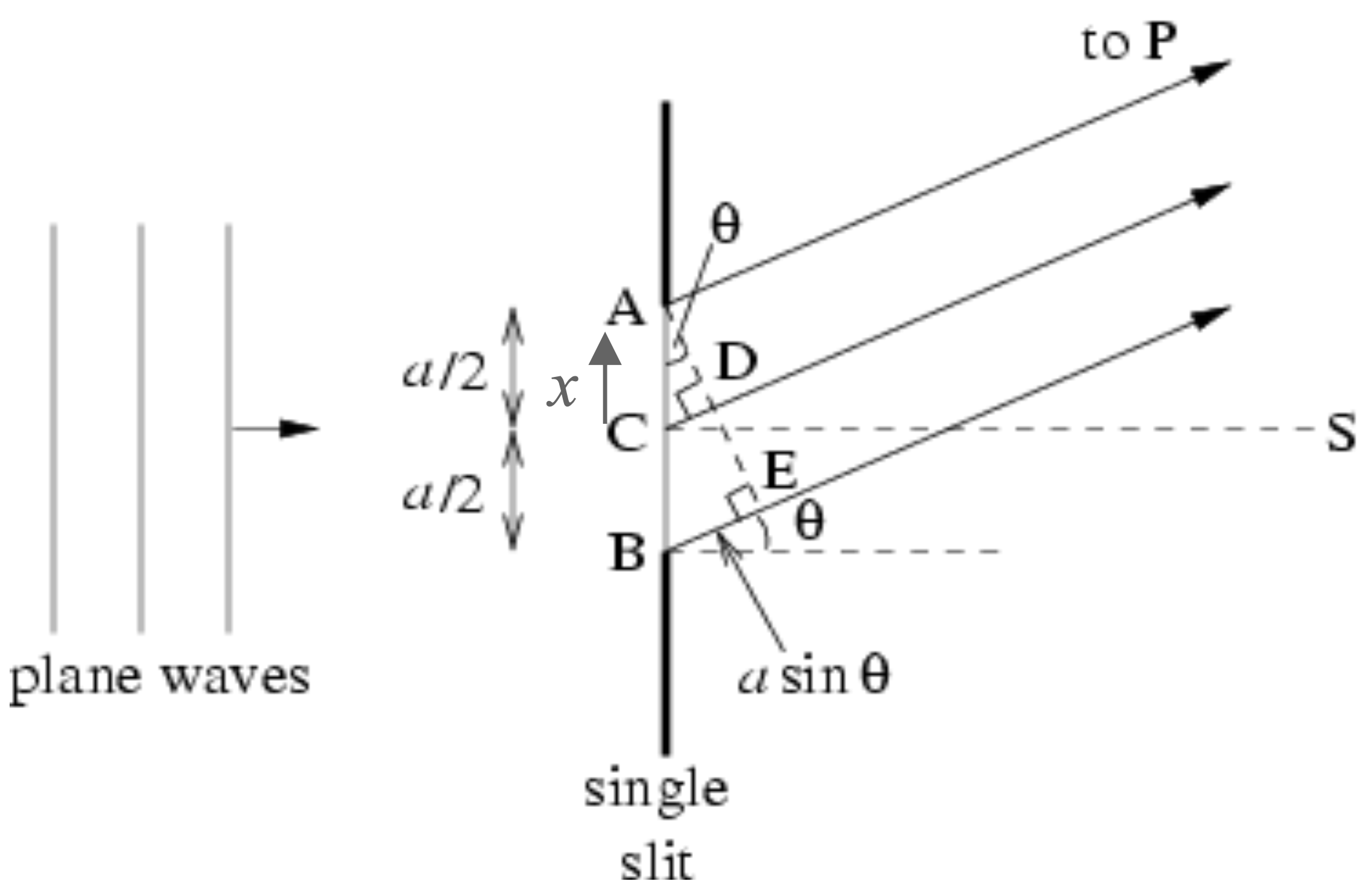
We will first consider a slit of width \(a\) with a midpoint \(C\) on the diagram, and split it up into point sources of width \(\delta x\). We will then define our ‘amplitude per unit length’ to be \(A = \frac{A_\text{max}}{a}\) so that each wave emanating from a point source has an amplitude of \(A \delta x\). Relative to the midpoint, each contribution from the point source between \(x + \delta x\) and \(x\) is given by \(A\delta x \times \cos (\omega t - k (r + x \sin \theta))\), where \(r\) is the distance from \(C\) to the point \(P\) on the screen. We can write each contribution as a phasor:
\[\delta Z = A e^{i(\omega t - kx - kx \sin \theta)} \delta x = A e^{i(\omega t - kx)} e^{- i k x \sin \theta} \delta x\]Summing up all of these contributions (for \(-a/2 \leq x \leq a/2\)) will therefore amount to computing an integral, given by:
\[\begin{aligned} Z &= A e^{i(\omega t - kx)} \int^{a/2}_{-a/2} e^{- i k x \sin \theta} dx \\ &= e^{i(\omega t - kx)} \frac{iA_\text{max}}{ka \sin \theta} (e^{- \frac{1}{2} i k a \sin \theta} - e^{ \frac{1}{2} i k a \sin \theta}) \\ &= e^{i(\omega t - kx)} \frac{iA_\text{max}}{\phi} \times -2i \sin (\frac{\phi}{2}) \\ &= e^{i(\omega t - kx)} A_\text{max} \text{sinc} ( \frac{\phi}{2} ) \end{aligned}\]Where we have written the overall phase difference between the top and bottom of the slit as \(\phi = k a \sin \theta\). This is the correct expression for the amplitude, giving \(I(\theta) = A^2_\text{max} \text{sinc}^2 ( \frac{\phi}{2} )\).
We can also use the integration approach to derive the diffraction pattern for the case of two slits, each of width \(a\), with midpoints separated by a distance \(d\). The midpoints of the top and bottom slits lie at \(x = \pm\frac{d}{2}\). We will therefore have contributions of waves from two regions: the top slit, where \(\frac{d}{2} + \frac{a}{2} \geq x \geq \frac{d}{2} - \frac{a}{2}\), and the bottom slit where \(-\frac{d}{2} + \frac{a}{2} \geq x \geq -\frac{d}{2} - \frac{a}{2}\). Since the combined width of the slits is \(2a\), we will set \(A = \frac{A_\text{max}}{2a}\). We then need to integrate over those contributions, to obtain:
\[\begin{aligned} Z &= A e^{i(\omega t - kx)} \left( \int^{d/2 + a/2}_{d/2 -a/2} e^{- i k x \sin \theta} dx + \int^{-d/2 + a/2}_{-d/2 -a/2} e^{- i k x \sin \theta} dx \right) \\ &= e^{i(\omega t - kx)} \frac{iA_\text{max}}{2ka \sin \theta} \left( e^{- i k \sin \theta (d/2 + a/2)} - e^{- i k \sin \theta (d/2 - a/2)} + e^{i k \sin \theta (d/2 - a/2)} - e^{i k \sin \theta (d/2 + a/2)} \right) \\ &= e^{i(\omega t - kx)} \frac{iA_\text{max}}{2ka \sin \theta} \left( -2i \sin (k \sin \theta (d/2 + a/2)) + 2i \sin (k \sin \theta (d/2 - a/2)) \right) \\ &= e^{i(\omega t - kx)} \frac{A_\text{max}}{ka \sin \theta} \left( \sin (k \sin \theta (d/2 + a/2)) - \sin (k \sin \theta (d/2 - a/2)) \right) \end{aligned}\]At this point, we want to apply the identity \(\sin \alpha - \sin \beta = 2 \cos (\frac{\alpha + \beta}{2}) \sin (\frac{\alpha - \beta}{2})\). This will yield:
\[\begin{aligned} Z &= e^{i(\omega t - kx)} \frac{2A_\text{max}}{ka \sin \theta} \cos (\frac{k d \sin \theta}{2} ) \sin (\frac{k a \sin \theta}{2} ) \\ &= e^{i(\omega t - kx)} \times A_\text{max} \cos (\frac{k d \sin \theta}{2} ) \text{sinc} (\frac{k a \sin \theta}{2} ) \end{aligned}\]Which is the exact same expression as before, modulated by the factor of \(\cos (\frac{k d \sin \theta}{2} )\). Overall, we get the following expression for intensity:
\[I(\theta) = A^2_\text{max} \cos^2 (\frac{k d \sin \theta}{2} ) \text{sinc}^2 (\frac{k a \sin \theta}{2} )\]
Finally, let’s relate our answer to Question 18 (b) from your problem sheets. There, we had a single slit of width \(a\), for which the middle third was blocked. We were asked to describe the resulting diffraction pattern:

From the above discussion it should be clear that the pattern for part (a) is given by the the single-slit diffraction intensity. In the second part, we can make use of our newly derived expressions. Since a third of the single slit is blocked, we obtain a double slit of width \(a \rightarrow \frac{a}{3}\), with the distance between the midpoints of the two slits being \(d \rightarrow \frac{2a}{3}\). Substituting this in, the exact formula for the resulting diffraction pattern intensity is given by (taking \(\phi = \frac{ka \sin \theta}{3}\)):
\[I(\theta) = A^2_\text{max} \cos^2 (\frac{k a \sin \theta}{3} ) \text{sinc}^2 (\frac{k a \sin \theta}{6} ) = A^2_\text{max} \cos^2 ( \phi ) \text{sinc}^2 (\frac{\phi}{2} )\]Which my students may recognise as the formula we derived in the supervision :-)